Build Your Own Experimental LoRaWAN Sensor
I wrote an Arduino wrapper for my LoRaWAN implementation. This post shows how to use it in an experimental application.
Note that even though the wrapper is very easy to use, you should not use it unless you know what you are doing. This includes knowing if you are allowed to do this where you live, and how much trouble you might get into if you interfere with other radio users.
The Application
Lately it’s been hot in Britain. Too hot. I want to know how hot it is.
To do this I will run a sensor in my home that measures temperature and humidity every 30 minutes. The sensor will be mains powered and will use LoRaWAN to push the data to The Things Network (TTN). I will then collect the data and store it in a CSV file on my PC.
The Hardware
For this project I’m using an Adafruit Metro (ATMEGA328) configured for 3V3 operation, a Semtech SX1272MB2DAS shield, and a DHT11 sensor. The Semtech shield has a CE mark and comes with an antenna.
The hardware plugs together like so:
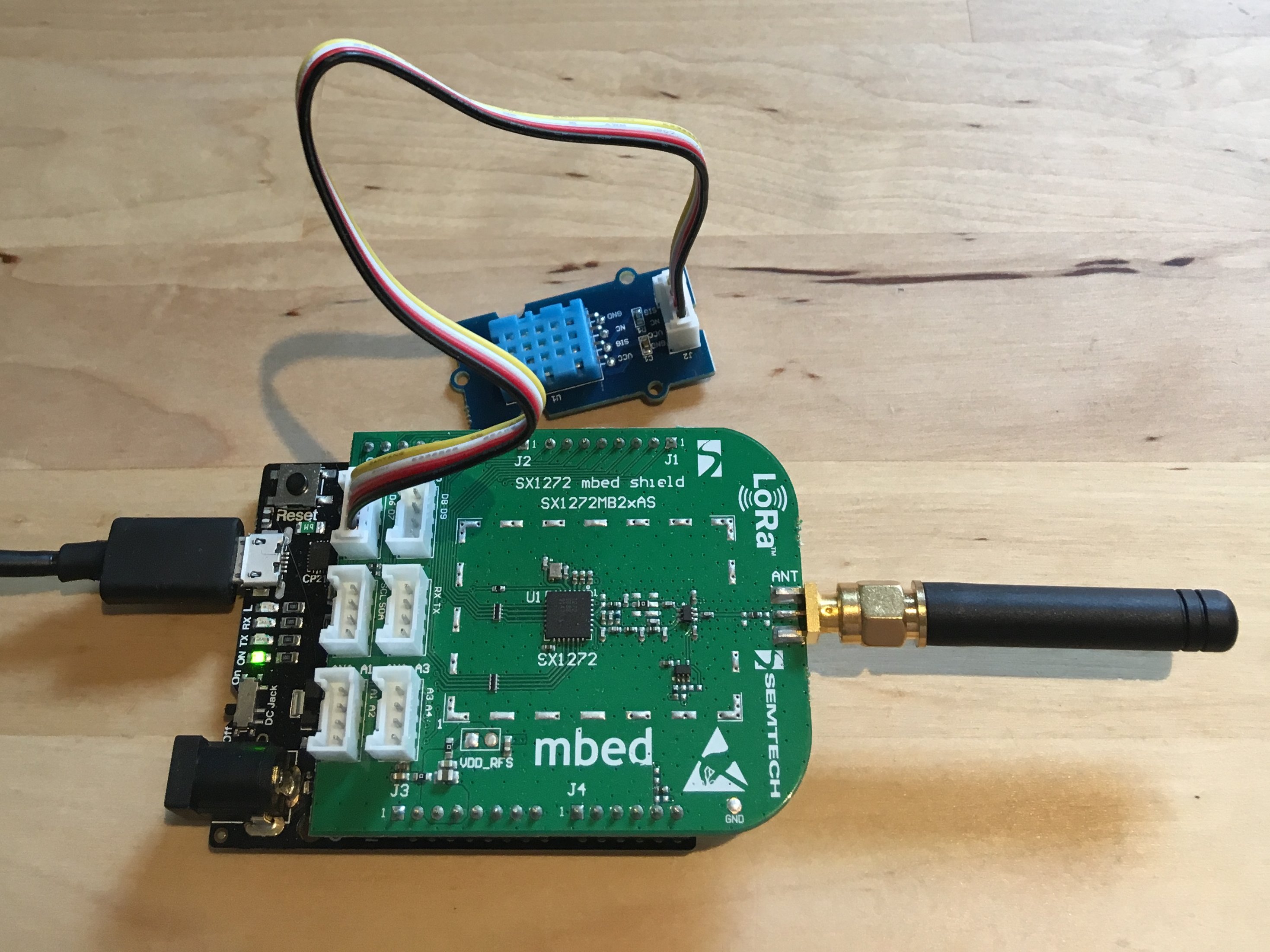
For a gateway I have a Multitech Conduit AP. If you are lucky you might not need one.
The Firmware
I wrote the following ino to meet my application requirements:
#define DEBUG_LEVEL 2
#include "src/arduino_ldl/arduino_ldl.h"
#include "src/Grove_Temperature_And_Humidity_Sensor/DHT.h"

const uint8_t devEUI[] PROGMEM = {0x00U,0x00U,0x00U,0x00U,0x00U,0x00U,0x00U,0x00U};
const uint8_t appEUI[] PROGMEM = {0x00U,0x00U,0x00U,0x00U,0x00U,0x00U,0x00U,0x00U};
const uint8_t appKey[] PROGMEM = {0x2bU,0x7eU,0x15U,0x16U,0x28U,0xaeU,0xd2U,0xa6U,0xabU,0xf7U,0x15U,0x88U,0x09U,0xcfU,0x4fU,0x3cU};

const uint32_t push_interval = 30UL*60UL*1000UL;
bool push;
uint32_t push_timer;

ArduinoLDL ldl(
    devEUI,
    appEUI,
    appKey,
    EU_863_870,         /* specify region */
    LORA_RADIO_SX1272,  /* specify radio */
    A0,                 /* radio reset pin */
    10,                 /* radio select pin */
    2,                  /* radio dio0 pin */
    3                   /* radio dio1 pin */
);

DHT dht(
    6,                  /* pin */
    DHT11               /* sensor type */
);

bool expired(uint32_t to)
{
    uint32_t time = millis();
    uint32_t delta = (to <= time) ? (time - to) : (UINT32_MAX - to + time);

    return (delta <= INT32_MAX);
}

void setup()
{
    Serial.begin(115200U);
    ldl.begin();
    dht.begin();

    ldl.setRate(5U);
    ldl.setPower(5U);
}

void loop()
{
    if(expired(push_timer)){

        push = true;
        push_timer = millis() + push_interval;
    }

    if(ldl.ready()){

        if(ldl.joined()){

            if(push){

                float buf[] = {
                    dht.readTemperature(),
                    dht.readHumidity()
                };

                ldl.unconfirmedData(1U, buf, sizeof(buf));

                push = false;
            }
        }
        else{

            ldl.otaa();
        }
    }

    ldl.process();
}
Compiling in the Arduino environment produces the following message:
Sketch uses 22158 bytes (68%) of program storage space. Maximum is 32256 bytes.
Global variables use 684 bytes (33%) of dynamic memory, leaving 1364 bytes for local variables. Maximum is 2048 bytes.
There’s still a bit of code space for extra features.
RAM usage seems OK but keep in mind that ldl.process() will use the stack to store the downstream frame, various keys, and a shadow instance of the session parameters. You probably need at least 500 bytes free to ensure the wheels don’t fall off.
Firmware Explanation
Includes
#define DEBUG_LEVEL 2
#include "src/arduino_ldl/arduino_ldl.h"
#include "src/Grove_Temperature_And_Humidity_Sensor/DHT.h"
Here the preprocessor is used to include the ArduinoLDL header.
Defining DEBUG_LEVEL before the include will enable a set of inline diagnostic messages. Level 1 gives a summary of state transitions, level 2 also includes parameters.
The DHT11 library header is needed to interface with the temperature and humidity sensor.
Mandatory LoRaWAN Parameters
const uint8_t devEUI[] PROGMEM = {0x00U,0x00U,0x00U,0x00U,0x00U,0x00U,0x00U,0x00U};
const uint8_t appEUI[] PROGMEM = {0x00U,0x00U,0x00U,0x00U,0x00U,0x00U,0x00U,0x00U};
const uint8_t appKey[] PROGMEM = {0x2bU,0x7eU,0x15U,0x16U,0x28U,0xaeU,0xd2U,0xa6U,0xabU,0xf7U,0x15U,0x88U,0x09U,0xcfU,0x4fU,0x3cU};
These byte strings are required to connect to TTN. TTN has plenty of resource explaining the purpose of these strings and where they come from so I won’t explain here.
These aren’t the values I actually used. What you see here is just filler.
The PROGMEM attribute is a quirky thing needed on AVR to ensure strings end up in flash memory rather than SRAM.
ArduinoLDL Construction
ArduinoLDL ldl(
    devEUI,
    appEUI,
    appKey,
    EU_863_870,         /* specify region */
    LORA_RADIO_SX1272,  /* specify radio */
    A0,                 /* radio reset pin */
    10,                 /* radio select pin */
    2,                  /* radio dio0 pin */
    3                   /* radio dio1 pin */
);
The constructor caches the settings but doesn’t perform any initialisation. Initialisation is done later in setup() by ldl.begin().
The two-step pattern is slightly awkward solution to two problems:
- The static object is constructed before the Arduino environment is initialised (so you should avoid touching the Arduino interfaces)
- The core implementation needs a pointer to the ArduinoLDL instance (which is not possible to know in the constructor)
DHT11 Construction
DHT dht(
    6,                  /* pin */
    DHT11               /* sensor type */
);
Here an instance of the sensor object is constructed by specifying the pin the sensor is connected to, and the hardware variant.
Application Timer
const uint32_t push_interval = 30UL*60UL*1000UL;
bool push;
uint32_t push_timer;

// snip

bool expired(uint32_t to)
{
    uint32_t time = millis();
    uint32_t delta = (to <= time) ? (time - to) : (UINT32_MAX - to + time);

    return (delta <= INT32_MAX);
}
This code is used in loop() to generate a push event every 30 minutes based on the Arduino millisecond counter.
setup()
void setup()
{
    Serial.begin(115200U);
    ldl.begin();
    dht.begin();

    ldl.setRate(5U);
    ldl.setPower(5U);
}
This function is called once from Arduino main() after the environment is initialised but before loop() is called.
Serial must be initialised to support the optional ArduinoLDL diagnostic messages. DHT and ArduinoLDL instances must also be initialised here by calling their begin() methods.
After initialisation the rate and power settings can be adjusted. I recommend using the lowest transmit power and spreading factor you can get away with.
The meaning of these integers changes depending on which region you specify in the ArduinoLDL constructor. You can read about it in the LoRaWAN Regional Parameters companion specification.
loop()
Loop is called repeatedly from Arduino main().
void loop()
{
    if(expired(push_timer)){

        push = true;
        push_timer = millis() + push_interval;
    }

    if(ldl.ready()){

        // snip
    }

    ldl.process();
}
Three things happen at the base of the loop:
First there is a check for if the application timer has expired. If it has, the push flag is set and push_timer is reset to the next interval.
Next there is a check for if ArduinoLDL is ready. ArduinoLDL must be ready before it will initiate a join or send data. ArduinoLDL is ready when:
- chip initialisation is complete, and
- there are no active operations (e.g. transmit/receive in progress), and
- a channel is available
Finally ldl.process() is called to make ArduinoLDL process events.
Drilling into the ldl.ready() branch:
    if(ldl.ready()){

        if(ldl.joined()){

            // snip
        }
        else{

            ldl.otaa();
        }
    }
When ArduinoLDL is ready but not joined to the network, it will attempt to join using ‘over the air activation’.
If ldl.otaa() completes successfully, ldl.joined() will return true, which will open up this branch:
        if(ldl.joined()){

            if(push){

                float buf[] = {
                    dht.readTemperature(),
                    dht.readHumidity()
                };

                ldl.unconfirmedData(1U, buf, sizeof(buf));

                push = false;
            }
        }
If the push flag is set, the firmware reads the sensor and sends the data using the unconfirmed data service on port 1.
The push flag is cleared after initiating the send. This ensures the send will not occur again until ArduinoLDL is ready and the application timer has expired.
Serial Monitor and TTN Console
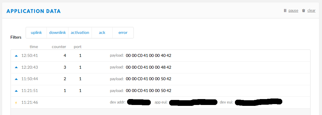
Running the sensor for two hours will produce serial monitor output which looks like this:
[520]RESET
[11936]STARTUP
[60304716]TX_BEGIN: SZ=23 F=868500000 SF=7 BW=125 P=5
[60367124]TX_COMPLETE
[65342284]RX1_SLOT: F=868500000 SF=7 BW=125
[65443864]DOWNSTREAM: SZ=33 RSSI=-62 SNR=10
[65450208]JOIN_COMPLETE
[65981800]TX_BEGIN: SZ=21 F=867300000 SF=7 BW=125 P=5
[66039092]TX_COMPLETE
[67034196]RX1_SLOT: F=867300000 SF=7 BW=125
[68016644]RX2_SLOT: F=869525000 SF=9 BW=125
[68054048]DATA_COMPLETE
[1800531712]TX_BEGIN: SZ=21 F=868300000 SF=7 BW=125 P=5
[1800588980]TX_COMPLETE
[1801584120]RX1_SLOT: F=868300000 SF=7 BW=125
[1802566600]RX2_SLOT: F=869525000 SF=9 BW=125
[1802603968]DATA_COMPLETE
[3600531348]TX_BEGIN: SZ=21 F=867100000 SF=7 BW=125 P=5
[3600588612]TX_COMPLETE
[3601583756]RX1_SLOT: F=867100000 SF=7 BW=125
[3602566244]RX2_SLOT: F=869525000 SF=9 BW=125
[3602603608]DATA_COMPLETE
[1105564436]TX_BEGIN: SZ=21 F=868100000 SF=7 BW=125 P=5
[1105621700]TX_COMPLETE
[1106616840]RX1_SLOT: F=868100000 SF=7 BW=125
[1107599316]RX2_SLOT: F=869525000 SF=9 BW=125
[1107636680]DATA_COMPLETE
You should also be able to see activity on the TTN console:
Collecting Data from TTN
I had originally planned to use the TTN HTTP integration to POST upstream messages to a Google Sheet. This didn’t work as expected and proved too difficult to debug in the time available.
I decided instead to use the MQTT interface. One useful feature of this protocol is that the client can receive messages from behind NAT. This means you can get started with something simple running on your PC, like this program I wrote in Ruby:
require 'mqtt'
require 'base64'
require 'json'

MQTT::Client.connect(
  :host => 'eu.thethings.network',
  :port => 8883,
  :ssl => true,
  :username => 'environment-sensor',
  :password => 'this-should-be-the-application-key'
) do |c|

  c.subscribe("environment-sensor/devices/+/up")

  puts "time,dev_id,hardware_serial,temperature,humidity"

  c.get do |t, m|

    data = JSON.parse(m)

    temperature, humidity = Base64.decode64(data['payload_raw']).unpack("ff")

    puts "#{data['metadata']['time']},#{data['dev_id']},#{data['hardware_serial']},#{temperature},#{humidity}"

  end

end
The program subscribes to upstream messages from all devices in my ‘environment-sensor’ application. Received messages are unpacked and printed to stdout in CSV format.
Running the program and the sensor at the same time should produce output that looks like this:
$ ruby listen.rb
time,dev_id,hardware_serial,temperature,humidity
2018-08-17T10:21:51.616432507Z,sensor1,<redacted>,24.0,52.0
2018-08-17T10:50:44.766045205Z,sensor1,<redacted>,24.0,52.0
2018-08-17T11:20:43.282121472Z,sensor1,<redacted>,24.0,50.0
2018-08-17T11:50:41.809375253Z,sensor1,<redacted>,24.0,48.0
And that’s it.